Paper Titled Electric Motor Author Unknown Date Unknown
- Title
- Paper Titled Electric Motor Author Unknown Date Unknown
- Accession Number
- 2020.3.369
- Accession Date
- 25 June 2024
- Accession Creator
- Robert Martinez
- Depositor
- Bobby Barton
- Format
- Paper
- Storage Location
- Modernization Records Box Folder #11
- Text
-
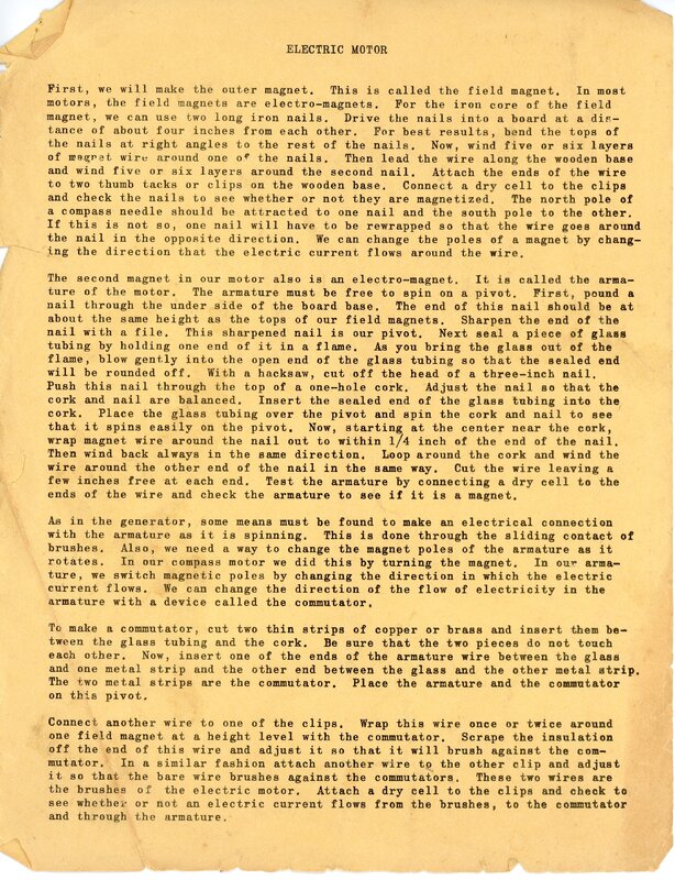
[Page One]
ELECTRIC MOTOR
First, we will make the outer magnet. This is called the field magnet. In most
motors, the field magnets are electric-magnets. For the iron core of the field
magnet, we can use two long iron nails. Drive the nails into the board at a dis-
tance of about four inches from each other. For best results, bend the tops of
the nails at right angles to the rest of the nails. Now, wind five or six layers
of magnet wire around one of the nails. Then lead the wire along the wooden base
and wind five or six layers around the second nail. Attach the ends of the wire
to two thumb tacks or clips on the wooden base. Connect a dry cell to the clips
and check the nails to see whether or not they are magnetized. The north pole of
a compass needle should be attracted to one nail and the south pole to the other.
If this is not so, one nail will have to be rewrapped so that the wire goes around
the nail in the opposite direction. We can change the poles of a magnet by chang-
ing the direction that the electric current flows around the wire.
The second magnet in our motor also is an electro-magnet. It is called the arma-
ture of the motor. The armature must be free to spin on a pivor. First, pound a
nail through the under side of the board base. The end of this nail should be at
about the same height as the tops of our field magnet. Sharpen the end of the
nail with a file. This sharpened nail is our pivot. Next seal a piece of glass
tubing by holding one end of it in a flame. As you bring the glass out of the
flame, blow gently into the open end of the glass tubing so that the sealed end
will be rounded off. With a hacksaw, cut off the head of a three-inch nail.
Push this nail through the top of a one-hole cork. Adjust the nail so that the
cork and nail are balanced. Insert the sealed end of the glass tubing into the
cork. Place the glass tubing over the pivot and spin the cork and nail to see
that it spins easily on the pivot. Now, starting at the center near the cork,
wrap magnet wire around the other end of the nail in the same way. Cut the wire leaving a
few inches free at each end. Test the armature by connecting a dry cell to the
ends of the wire and check the armature to see if it is a magnet.
As in the generator, some means must be found to make an electrical connection
with the armature as it is spinning. This is done through the sliding contact of
brushes. Also, we need a way to change magnet poles of the armature as it
rotates. In our compass motor we did this by turning the magnet. In our arma-
ture, we switch magnetic poles by changing the direction in which the electric
current flows. We can change the direction of the flow of electricity in the
armature with a device called the commutator.
To make a commutator, cut two thin strips of copper or brass and insert them be-
tween the glass tubing and the cork. Be sure that the two pieces do not touch
each other. Now, insert one of the ends of the armature wire between the glass
and one metal strip and the other end between the glass and the other metal strip.
The two metal strips are the commutator. Place the armature and the commutator
on this pivot.
Connect another wire to one of the clips. Wrap this wire once or twice around
one field magnet at a height level with the commutator. Scrape the insulation off the end of this wire and adjust it so that it will brush against the com-
mutator. In a similar fashion attach another wire to the other clip and adjust
it so that the bare wire brushes against the commutators. These two wires are
the brushes of the electric motor. Attach a dry cell to the clips and check to
see whether or not an electric current flows from the brushes, to the commutator
and through the armature.
[End of Page One]
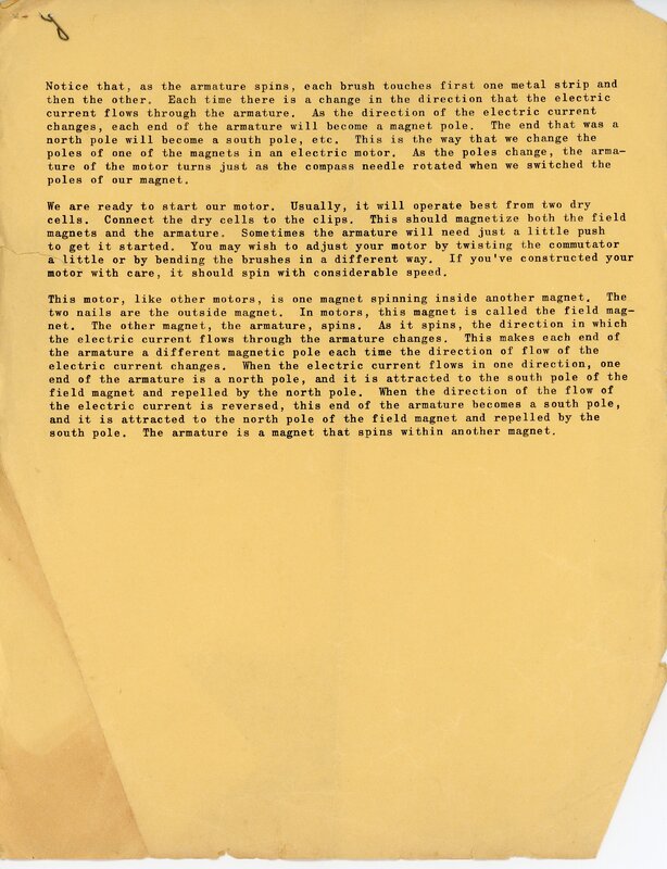
[Page Two]
Notice that, as the armature spins, each brush touches first one metal strip and
then the other. Each time there is a change in the direction that the electric
current flows through the armature. As the direction of the electric current
changes, each end of the armature will become a magnet pole. The end that was a
north pole will become a south pole, etc. This is the way that we change the
poles of one of the magnets in an electric motor. As the poles change, the arma-
ture of the motor turns just as the compass needle rotated when we switched the
poles of our magnet.
We are ready to start our motor. Usually, it will operate best from two dry
cells. Connect the dry cells to the clips. This should magnetize both the field
magnets and the armature. Sometimes the armature will need just a little push
to get it started. You may wish to adjust your motor by twisting the commutator
a little or by bending the brushes in a different way. If you've constructed your
motor with care, it should spin with considerable speed.
This motor, like other motors, is one magnet spinning inside another magnet. The
two nails are the outside magnet. In motors, this magnet is called the field mag-
net. The other magnet, the armature, spins. As it spins, the direction in which
the electric current flows through the armature changes. This makes each each end of the
armature a different magnetic pole each time the direction of flow of the
electric current changes. When the electric current flows in one direction, one
end of the armature is a north pole, and it is attracted to the south pole of the
field magnet and repelled by the north pole. When the direction of the flow of
the electric current is reversed, this end of the armature becomes a south pole,
and it is attracted to the north pole of the field magnet and repelled by the
south pole. The armature is a magnet that spins within another magnet.
[End of Page two]
Part of Paper Titled Electric Motor Author Unknown Date Unknown

